Kevin Guo
CERA: Ceramic Extruding Robot Arm
January 2019 - December 2019
Kevin Guo, Madeleine Eggers, Karolina Piorko, Veronika Varga, Jenny Sabin
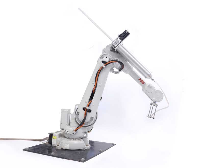
For Spring 2019, I took Prof. Jenny Sabin's research seminar in Matter Design Computation. As part of the seminar, I worked on a brand-new extruder system for the lab's Sulla robotic arm, a system we call CERA (Ceramic Extruding Robot Arm). I continued work on it through the Summer and into Fall 2019.
Background
In the past, the Lab used a pneumatic ceramic extruder system used for RoboSense 2.0. This system had a few issues; the pneumatics were independent of the robot so there was no coordination between the robot and the extruder. Also, pneumatic controls were very coarse, only allowing for a change in pressure. For the next iteration of RoboSense, we wanted to make a fabrication method that would allow for the construction of fine detailed objects such as PolyBrick in an architectural scale.
Design
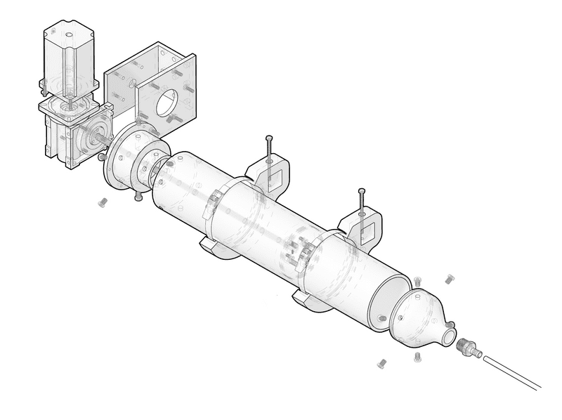
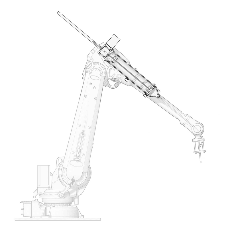 Cutaway diagram of CERA on robot arm
The overall design of CERA is centered around a 2ft long 4.5in diameter aluminum tube with a plunger inside. The plunger is attached to a leadscrew, which itself is driven by a worm gearbox. This gearbox is powered by a 1712oz-in NEMA34 Closed Loop Stepper Motor.
Mechatronics
Motor
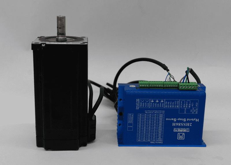 1712oz-in NEMA34 Closed Loop Stepper Motor
One of the first decisions that had to be made was which motor to use for the extruder. A stepper motor powered extruder was attempted before in the lab but had to be abandoned as discrepancies between the motor's reported and actual position made it virtually impossible use accurately. That ultimately blocked progress on RoboSense and forced it to be shelving until I arrived at the lab.
I stuck with using a stepper motor as I had used them extensively in previous roles and knew that a stepper would have the requisite torque to push clay through a tube. To deal with problems with positioning, I chose a closed-loop stepper motor system, a stepper motor with a built-in encoder that corrects for any discrepancies in motor position.
Machina
To command the robot, we decided upon Machina, an open-source framework for robots that allows for real-time control and feedback. This allowed for us to control the robot directly from either a PC Desktop or from Grasshopper without the need for predefining a sequence of actions or using RobotStudio, ABB's proprietary programming software for its robots. It also had a large set of commands that allow for a rich set of functionality including for digital I/O communication detailed below.
Digital I/O Communication
The next step was figuring out how to communicate between Grasshopper, the robot, and CERA all at once. The initial communication system involved using Firefly, a Grasshopper plugin for microcontrollers, to send Serial messages over a very long USB cable in this format: Steps/Pulse Width. So the Serial message 500/250 would be read by the Arduino as move 500 steps counterclockwise with a 250 µs delay in between pulses.
While this solution was simple to implement, it didn't solve the inherent separation between robot movement and extruder action that would inevitably create issues with fabrication down the road. There had to be a new system that allowed for native communication the robot to control the extruder and any other components attached.
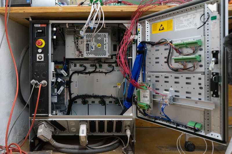
After some searching, I learned that the ABB IRC5 robot controller that we were using had a I/O module built in called an DSQC 652. More importantly, the DSQC 652 had 16 digital outputs. A digital output is only capable of spitting out a 1 or a 0, but that would be enough.
First Approach
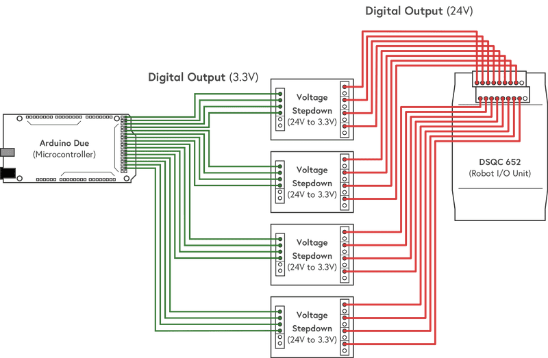 Schematic for the first digital communications system
My initial attempt to communicate between the Robot and our controller used all 16 digital outputs available (note: this is a bad idea). Each output would be a single digit in a 16 bit long binary number.
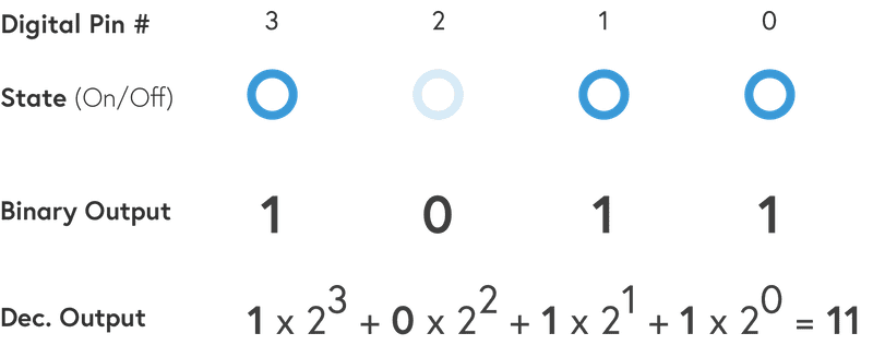 Example of a binary output for the number 11. (Note: for simplicity, there are only 4 outputs shown instead of the full 16)
Almost immediately, problems arose; all the intended outputs did not change at the same time, meaning that readings would be often times incorrect or wrong. Also, running 16 separate cables that had to be over 10ft (3 meters) long became very hard to deal with in the relatively tight confines we had at the lab. In retrospect, for such a system to work, there'd need to be a clock of some sort. This is why serial comm interfaces on most computers have 2 lines, a data line and a clock line that keeps everything in sync.
Final Approach
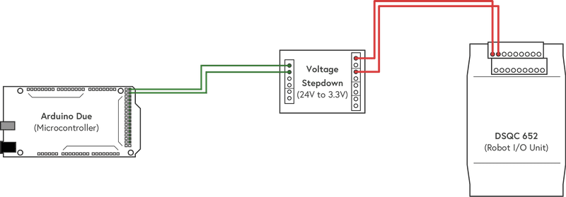 Schematic for the final digital communications system
The final approach to digital communications was vastly simplified from before. Two digital outputs from the ABB's I/O module are wired from the inside of the IRC5 controller, past a barrier wall, up the robot arm, and onto the mounting plate with the Arduino board. One digital output dictates which direction the stepper motor would turn (On means clockwise, Off means counter-clockwise), which dictates whether the extruder piston goes forward or back. The other digital output is an On/Off switch for the stepper motor; as long as the output was On, the motor would make another "step" and continue rotating.
These outputs made it very easy to synchronize actions between robot and extruder. As all commands went through Machina and therefore the robot, the sequence guaranteed extrusion concurrent with robot movement.
Example Command Sequence
| Command | What it does |
|---|---|
digitalWrite(DO10_2, True) |
Sets direction of motor to move plunger forward |
digitalWrite(DO10_1, True) |
Turns on stepper motor |
wait(<time in milliseconds>) |
Gives extruder some time to "prime" |
move(<some vector>) |
Moves robot a certain amount |
digitalWrite(DO10_1, False) |
Turns off stepper motor |
Overview of CERA's Mechatronics
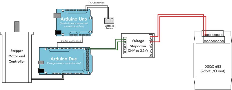 Schematic for all of CERA's Mechatronics
Commands from the Grasshopper and Machina scripts are sent via the robot's I/O unit to an Arduino Due. The Due in turn receives a digital reading from an Arduino Uno which is Off if the plunger mechanism is either too close to either end of the tube or On if it's at an acceptable distance (due to an inherent timing issue with the Arduino board, it can't the Due can't both drive the motor and read the distance sensor). Based on both these readings, the Arduino Due sends an Step pulses and Direction signal to the Stepper motor controller, which then turns the motor and moves the plunger up and down.
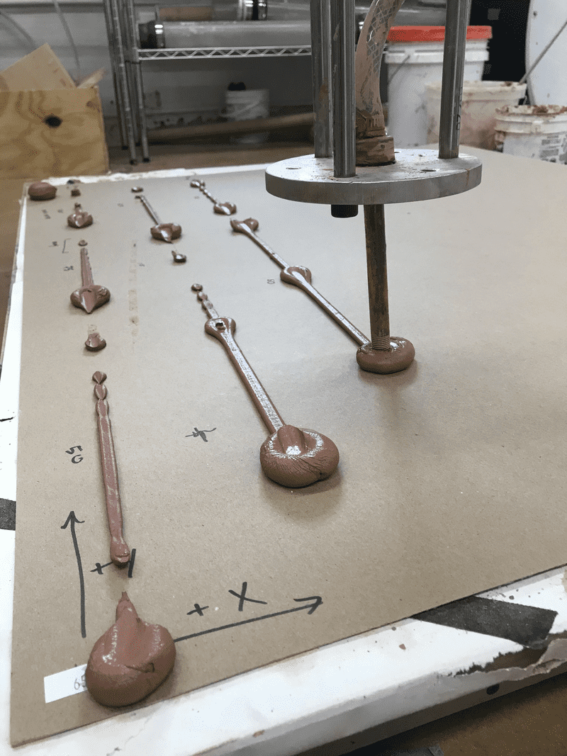
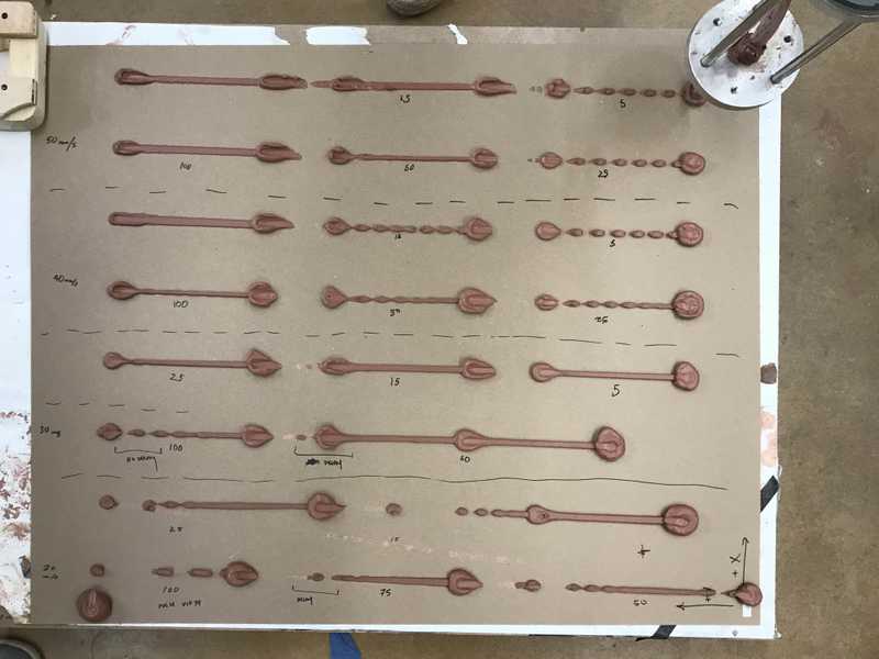 Full results of first CERA line test
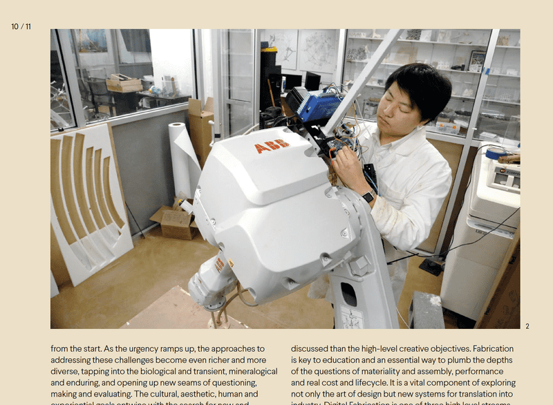 CERA and I were featured in a photo in Fabricate 2020
